
Technical Documentation
Drawings
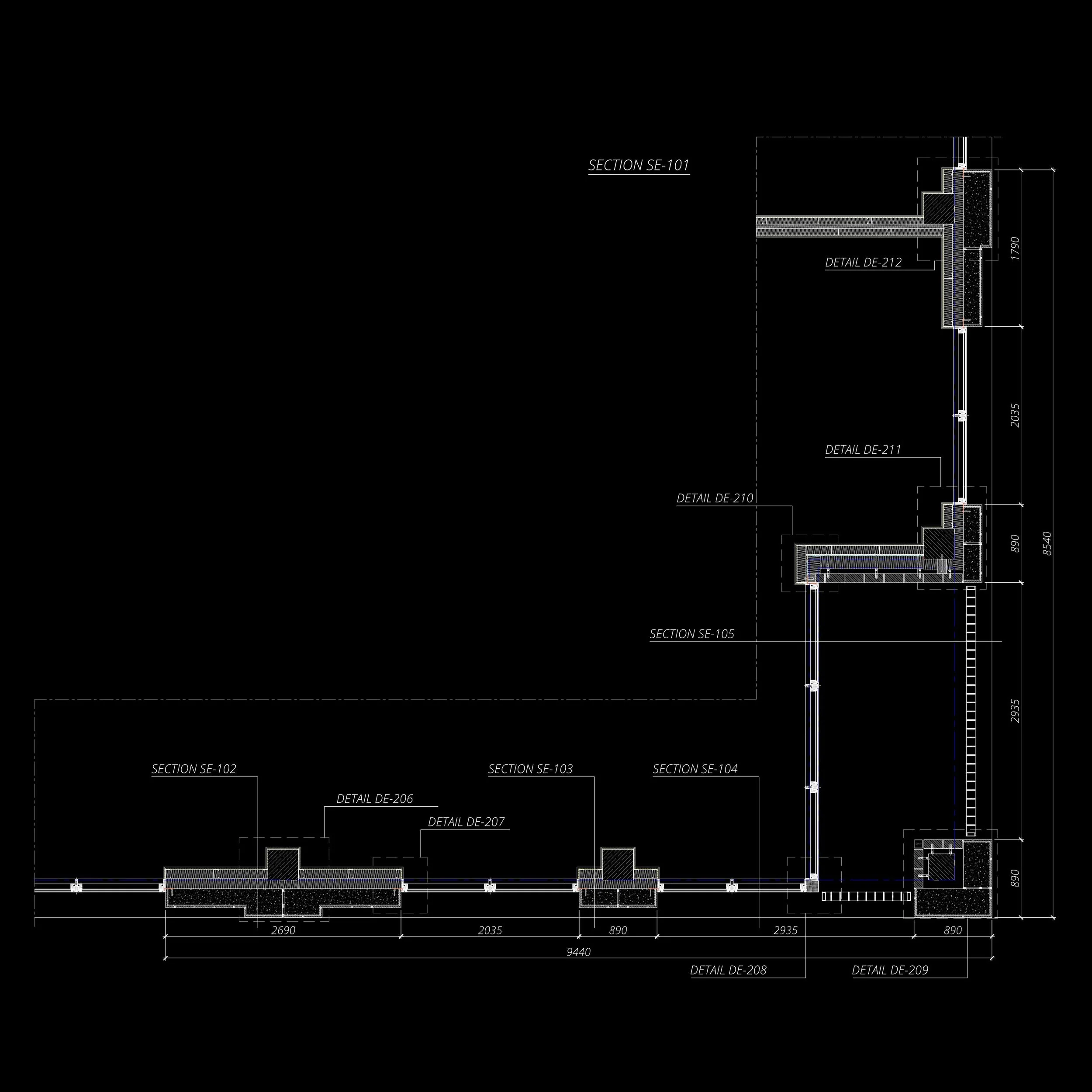
Architectural section drawing with labeled details and sections, including SE-101, SE-102, SE-103, and specific detail notes like DE-212, DE-211, on a black background.

Architectural section drawing with measurements and details labeled SE-102 and DE-201.

Architectural cross-section drawing labeled SE-103, showing structural details, dimensions, and construction elements.

Architectural section drawing labeled "SECTION SE-104," showing detailed dimensions and construction details for a structural wall. Includes measurements such as 665, 2500, 2335, 1120, and 300. The drawing indicates levels marked as FFL and a detail reference "DETAIL DE-203."
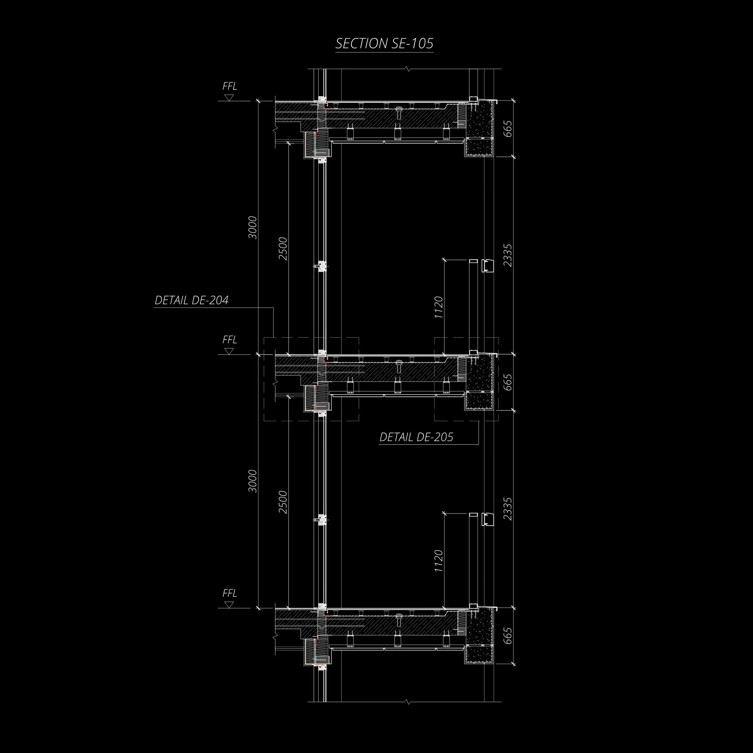
Architectural technical drawing of a building section, labeled SE-105, showing details such as dimensions, floor levels, and construction elements. It includes measurements for sections DE-204 and DE-205 on a black background.

Architectural technical drawing of building detail with measurements and labels on a black background.
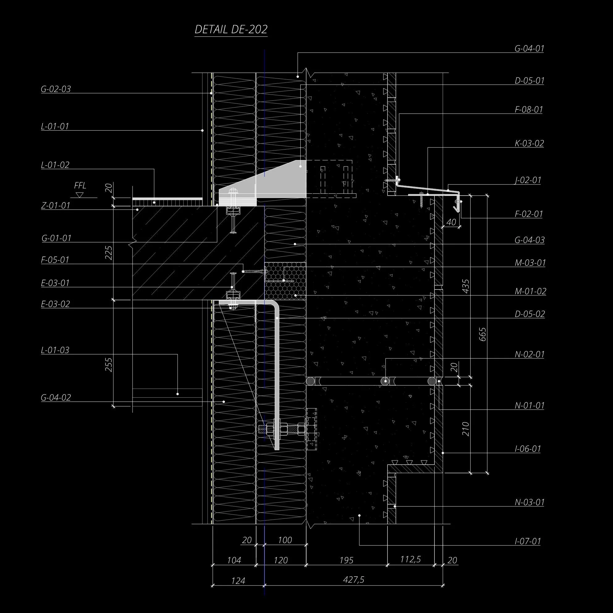
Architectural detail drawing labeled "Detail DE-202", showing cross-section of building wall with layers, dimensions, and construction elements.

Architectural detail drawing labeled DE-203 showing cross-section of building components with measurements and notes.
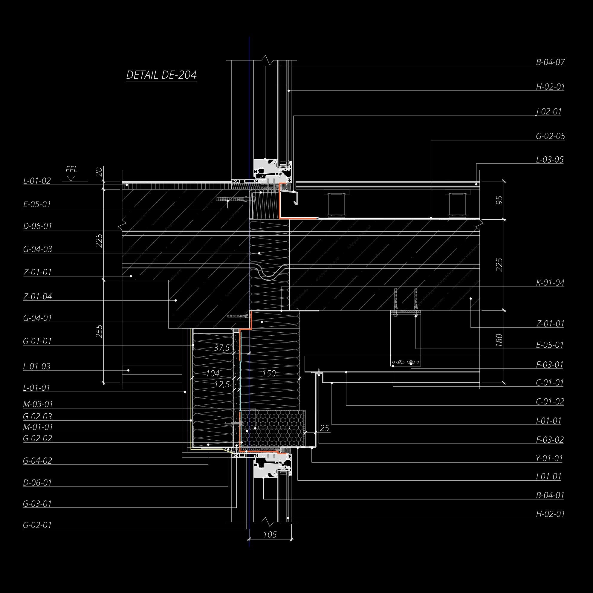
Technical architectural detail drawing labeled "DETAIL DE-204," showing cross-sectional analysis of building components with measurements and annotations.

Detailed architectural blueprint labeled "Detail DE-205" showing cross-sectional drawings with various measurements and specifications, including dimensions and structural components, on a black background.

Architectural drawing showing detailed section of a structural element with measurements and annotations, labeled as DETAIL DE-206. Includes dimensions and construction specifications.

Technical drawing labeled "Detail DE-207," showing a sectional view with dimensions, design elements, and construction details labeled G-01-01, I-01-01, G-04-02, etc.

Technical drawing of architectural detail labeled DE-208 with measurements
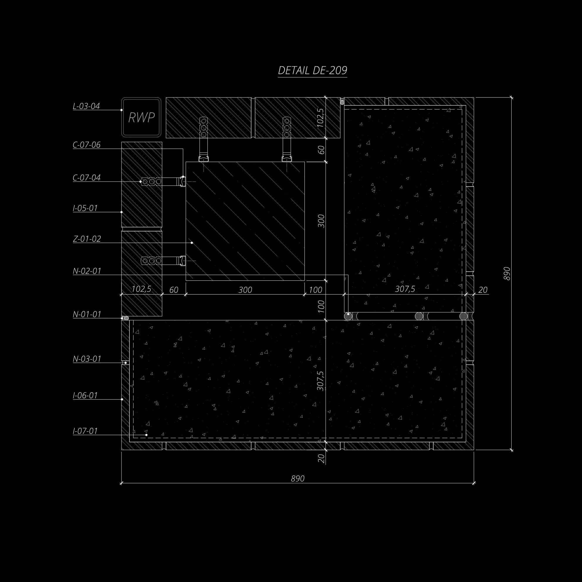
Technical drawing labeled "DETAIL DE-209" showing architectural details with measurements and labels, including sections marked "RWP" and various codes like L-03-04, C-07-06, and N-01-01.
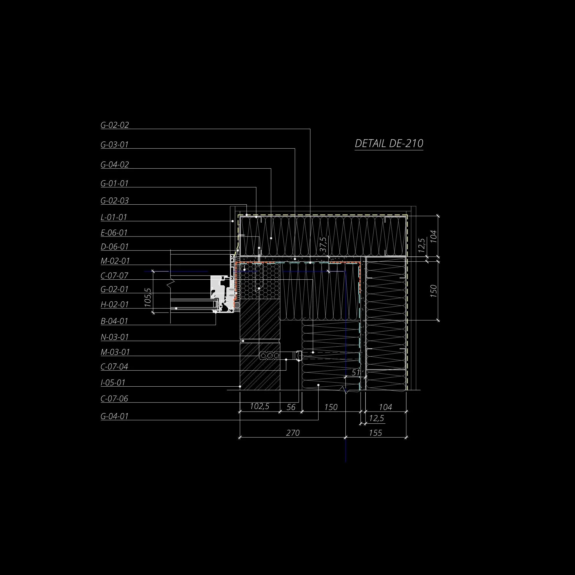
Technical drawing of a building detail labeled as DE-210, featuring various measurements and annotations. Includes dimensions and material specifications, with lines and symbols indicating structural components on a black background.

Architectural technical drawing detail with labeled dimensions and materials, titled "DETAIL DE-211."

Technical architectural section drawing with measurements and annotations, detailing building components.
Thermal Performance Analysis

3D building section with thermal analysis overlay, showing temperature gradient across roof and wall surfaces; color scale from -2°C to 21°C indicates thermal performance. Flixo software logo included.

3D thermal analysis of a building exterior wall assembly with color-coded temperature gradient, showing areas of heat loss and insulation, and labeled with humidity and dew point indicators. Software logo in bottom right corner.

Thermal bridge analysis of building wall with color-coded temperature variations, showing cold areas in blue and warm areas in red, humidity level at 60%, and dew point at 12.9°C. Flixo logo at bottom right.

3D building model with heat map showing thermal distribution; temperature scale ranges from -2°C to 21°C; humidity at 60%; flixo logo.

Thermal image showing heat transfer in a building wall, with color gradients indicating temperature changes. Includes humidity level at 60% and dew point at 12.9°C. Marked with 'Flixo' logo.

3D thermal analysis of a brick wall section with temperature gradient, color-coded to show heat distribution. Includes humidity information and labeled temperatures, with 'flixo' logo.
Boundary Condition
Internal T °C +21
External T °C -2
Humidity RH % 60
Dew point T °C +12.9
Heat Losses Analysis

Thermal analysis diagram of a window installation showing heat distribution in rainbow colors with Psi j, Ug, and Up values displayed. "Flixo" logo in the corner.
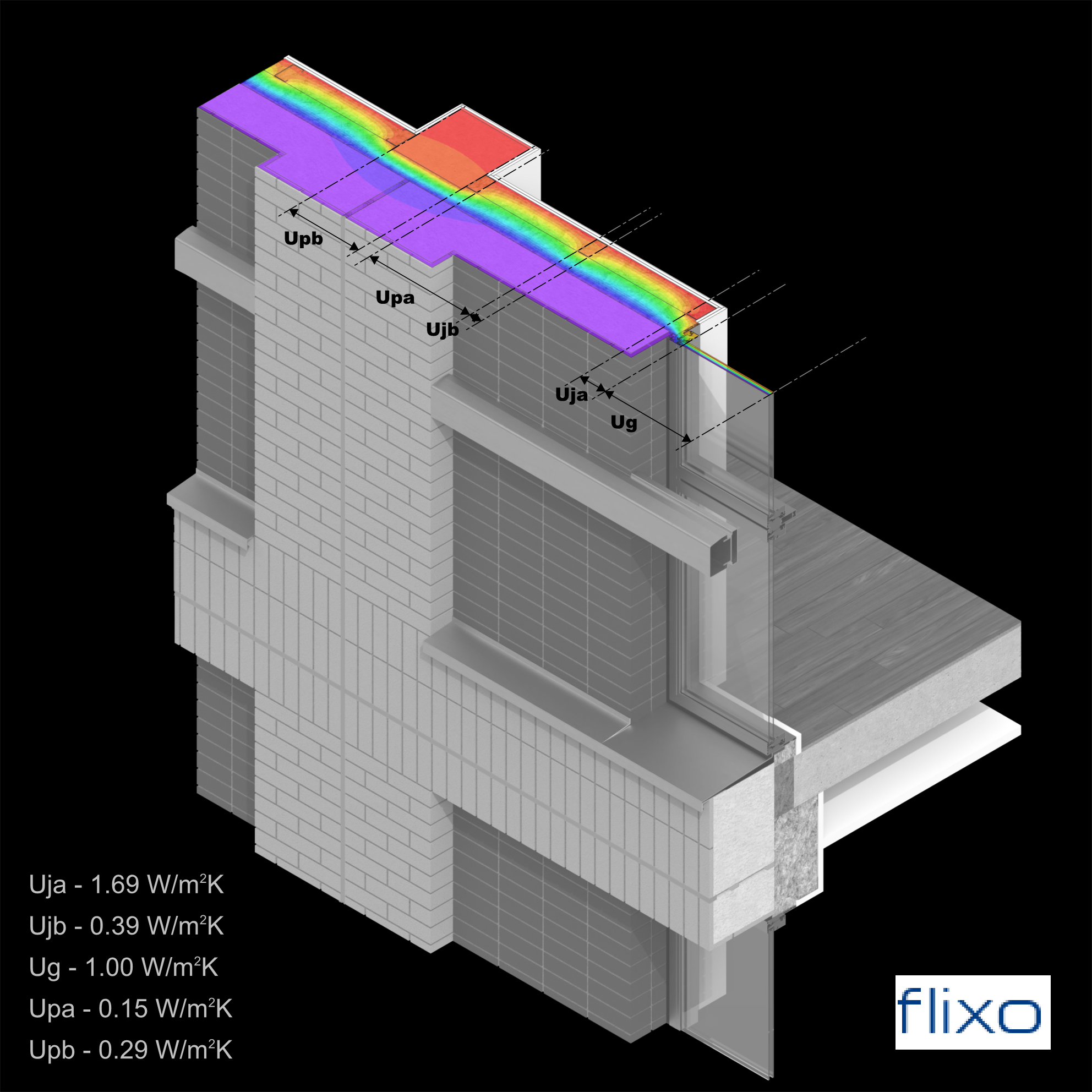
Thermal analysis diagram of a building façade showing heat flow distribution characterized by different colors, from red to blue, indicating temperature variations. The image includes labels such as Uja, Ujb, Ug, Upa, and Upb, with corresponding thermal transmittance values measured in W/m²K. The diagram also features a 3D visual representation of the building structure, and the logo 'Flixo' in the bottom right corner.
Boundary Condition
Internal T °C +20
External T °C 0