
Drawings

Architectural section drawing SE-101 showing detailed construction elements.

Architectural technical drawing, section SE-102 diagram

Technical CAD drawing of building section with labeled details SE-103, DE-206, and DE-207, showing dimensions and architectural components.

Technical architectural drawing of a building section labeled "SECTION SE-104."

Architectural technical drawing with detailed structural section view labeled "DETAIL DE-201," showing dimensions and construction layers.
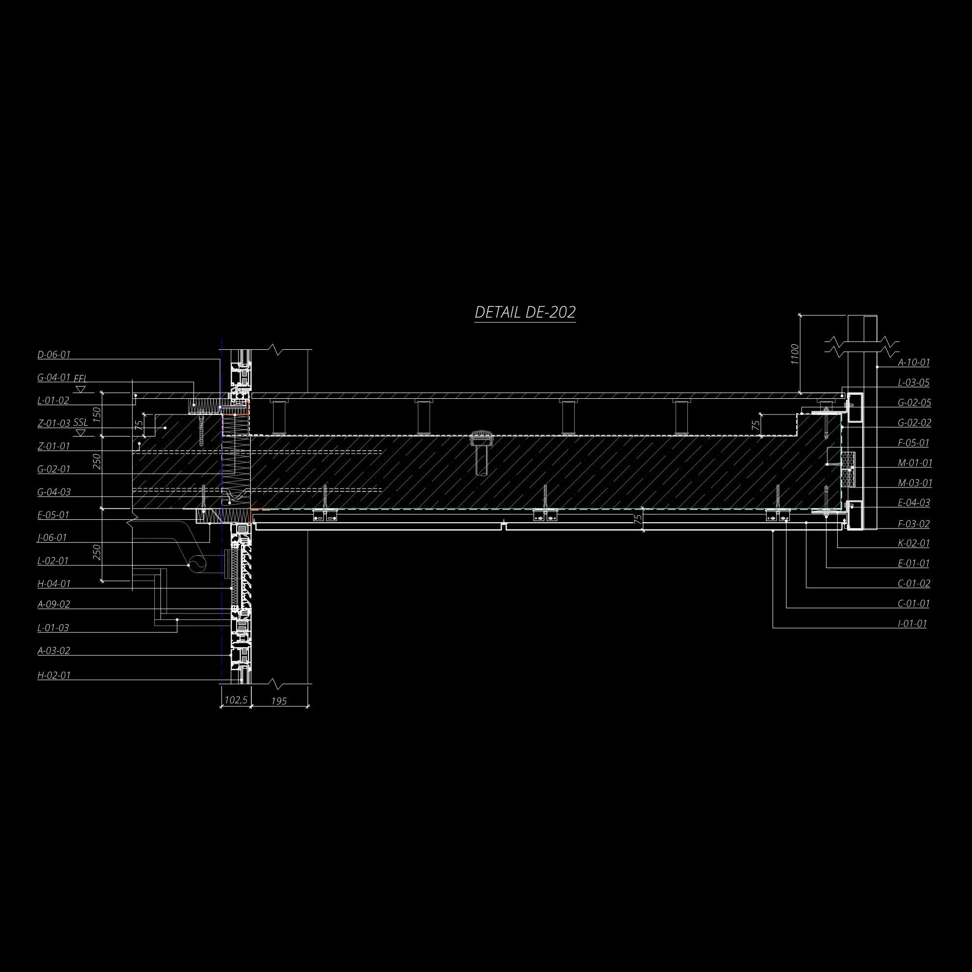
Architectural technical drawing labeled Detail DE-202 with measurements and material specifications.

Architectural technical drawing of building details with measurements and labels, annotated as Detail DE-203.

Detailed architectural section drawing of a building component, labeled as Detail DE-204, showing various layers and construction elements, including dimensions and annotations.

Architectural wall section detail drawing labeled "DETAIL DE-205" with dimensions and measurements. Various architectural layers and components are annotated with codes and lines indicating structural elements and materials.

Technical architectural drawing with dimensions and labels

Architectural technical drawing with detailed measurements and annotations

Architectural detail drawing labeled DE-208, showing dimensions and component specifications for a structural section. Measurements include 300, 325, 195, and 70. Includes labeled sections with codes: H-02-01, A-02-07, N-01-01, F-01-01, K-01-04, F-02-01, Z-01-02, L-01-01, G-04-01, I-01-01.

Architectural section detail labeled DE-209, showing layers and components of a building wall with measurements and material codes.

Detailed architectural section drawing labeled "DETAIL DE-210," showing various measurements and annotations with components and materials identified by alphanumeric codes, set against a black background.

Technical drawing labeled "DETAIL DE-211" illustrating architectural or engineering details with measurements and annotations. Includes various elements like walls, insulation, and structural components, marked with codes such as M-02-01 and G-02-02, and dimensions in millimeters.

Architectural detail drawing labeled "DETAIL DE-212" with measurements and technical symbols, showing building component specifications on a black background. Lines, numbers, and labels are in white, indicating various construction details.

Uj – 1.16 W/m2K; Ug - 1.00 W/m2K; Up - 0.11 W/m2K

Uj – 0.62 W/m2K; Up - 0.11 W/m2K

Uj – 1.52 W/m2K; Ug - 1.00 W/m2K; Up - 0.13 W/m2K

updated

updated

updated

updated

updated

updated

updated

updated

updated

updated
Condensation Risk. Boundary Conditions 1

Thermal analysis of building insulation with temperature gradient

Thermal analysis of a window assembly showing heat distribution with color gradient from red (hot) to purple (cold).

Thermal analysis of a building wall section showing temperature gradient and dew point with color scale.

3D building corner section showing heat distribution on a flat roof, with a color gradient indicating temperature changes. Features include brick facade, glass window, and a temperature scale bar.

Thermal analysis of a building's wall section, showing temperature distribution with a color gradient from blue to red. Includes a window corner detail and color scale indicating temperatures from -4°C to 20°C and dew point.

updated

updated

updated

updated
Condensation Risk. Boundary Conditions 2

3D building wall section with thermal gradient analysis

Thermal analysis of a building wall section with a window, showing temperature gradient using color spectrum from red (warm) to blue (cold).

3D visualization of a building facade section with heat transfer simulation, showing temperature gradient across materials.

Thermal analysis of a building section showing temperature distribution across walls and insulation, with a color gradient ranging from blue to red indicating temperature variation.

3D building section with thermal analysis color map, showing temperature distribution in Celsius on walls and roof.

updated

updated

updated

updated


